Elements of image quality...

I've tried to use the DoF calculator by changing f-number, CoC and focus distance, with CoC value set by segment, pixel pitch more or less 5um:
Pixel pitch is not a blur contributor. Pixel aperture is.
- CoC = f-number/1000 for f-numbers >> pixel pitch in um, assuming diffraction and DoF are the main contributors to blur. e.g for f-numbers f/11, f/16, f/22 etc.. CoC = 0.011, 0.016, 0.022 respectively. Balance DoF blur and diffraction blur.
You are making some assumptions that you haven't stated. What focus distance? What subject distance? Show the entire calculation, please.
- CoC = 0.01 constant for all f-numbers <= 10 (lens optical BW + sensor res. become dominant). e.g CoC = 0.01 for f/8, f/5.6, f4, f2.8 etc. This is under the assumption that the lens optical bandwidth + sensor res. are dominant, and that lens optical bandwidth is consistent with 5um pixel pitch, ignoring pixel aperture side effects.
The same point applies here.
The approximation works quite well, with the advantage that it is usable in the field, just using a DoF calculator on a smartphone.
One useful data point for your calculations: CoC equals defocus of the image plane over f-stop.
 
It was demonstrated that diffraction has an impact even at medium apertures.

Jim Kasson has a very nice example of that here:

From Jim Kassons article : https://blog.kasson.com/the-last-word/focus-shift-loca-of-fuji-1102-on-gfx/

From Jim Kassons article : https://blog.kasson.com/the-last-word/focus-shift-loca-of-fuji-1102-on-gfx/

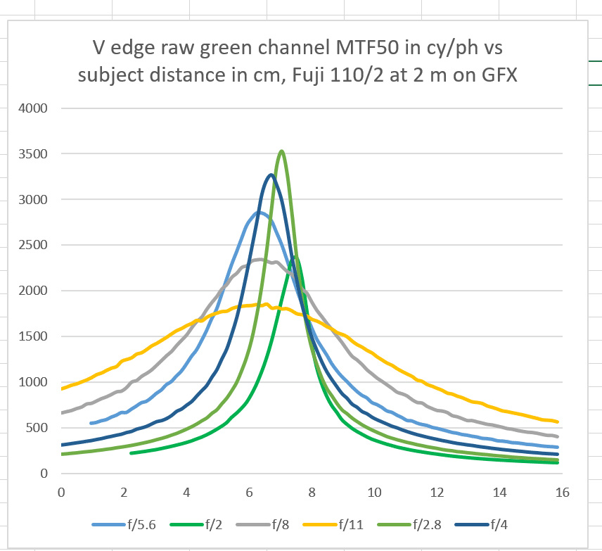
This shows MTF 50 for the GFX 110/2 near axis at different apertures. We can see that the f/2.8 curve peaks at around 3500 cy/PH. That is the best such value I ever have seen. To some extent, it is due to the undersize microlenses on the GFX 50.

This also shows that stopping down to f/11 MTF 50 drops to around 1800 cy/PH. That is still a very reasonable value, Something like what I can get with my present gear at optimal aperture.

But, this is without sharpening. In the real life we always have some sharpening. I don't have Jim's raw images, so I demonstrate with some of my own.


This plots are from a test with my Sonnar 180/4 at f/5.6 and at f/11. Here we can see a significant loss of sharpness going from f/5.6 to f/11.


But, we can apply some sharpening, here I sharpened with FocusMagic using a radius of 2 for both images but using a different strength 50% for f/5.6 and 75% for f/11. So the images are pretty much similarly sharp up to like 2/3 of the Nyquist limit.

I would probably prefer sharpening with less halos, this is just a quick demo.

What would that mean in practice? When viewing the whole image say in projection at 4K or in a reasonably sized print, I don't think the difference between the two sharpened pictures would be noticable, as the left side of the MTF curve is essentially the same.

Looking at actual pixels, there may be a difference, but both are a bit too sharp.

Jim Kasson has some nice write up on best sharpening on the GFX 50 and the GFX 100,

but I cannot find it right now. Good stuff, if you can live with quite a few graphs.

Best regards

Erik


--
Erik Kaffehr
Website: http://echophoto.dnsalias.net
Magic uses to disappear in controlled experiments…
Gallery: http://echophoto.smugmug.com
Articles: http://echophoto.dnsalias.net/ekr/index.php/photoarticles
 
It was demonstrated that diffraction has an impact even at medium apertures.

Jim Kasson has a very nice example of that here:

From Jim Kassons article : https://blog.kasson.com/the-last-word/focus-shift-loca-of-fuji-1102-on-gfx/

From Jim Kassons article : https://blog.kasson.com/the-last-word/focus-shift-loca-of-fuji-1102-on-gfx/

This shows MTF 50 for the GFX 110/2 near axis at different apertures. We can see that the f/2.8 curve peaks at around 3500 cy/PH. That is the best such value I ever have seen. To some extent, it is due to the undersize microlenses on the GFX 50.
This also shows that stopping down to f/11 MTF 50 drops to around 1800 cy/PH. That is still a very reasonable value, Something like what I can get with my present gear at optimal aperture.
But, this is without sharpening. In the real life we always have some sharpening. I don't have Jim's raw images, so I demonstrate with some of my own.

This plots are from a test with my Sonnar 180/4 at f/5.6 and at f/11. Here we can see a significant loss of sharpness going from f/5.6 to f/11.

But, we can apply some sharpening, here I sharpened with FocusMagic using a radius of 2 for both images but using a different strength 50% for f/5.6 and 75% for f/11. So the images are pretty much similarly sharp up to like 2/3 of the Nyquist limit.

I would probably prefer sharpening with less halos, this is just a quick demo.

What would that mean in practice? When viewing the whole image say in projection at 4K or in a reasonably sized print, I don't think the difference between the two sharpened pictures would be noticable, as the left side of the MTF curve is essentially the same.

Looking at actual pixels, there may be a difference, but both are a bit too sharp.

Jim Kasson has some nice write up on best sharpening on the GFX 50 and the GFX 100,

but I cannot find it right now. Good stuff, if you can live with quite a few graphs.
The Gaussian-like point spread functions in the region where pixel aperture, diffraction, and defocus are all significant are also candidates for either space-domain or frequency-domain sharpening. Pure defocus, not as much.

However, there's something your frequency-domain graphs don't show, and that is whether the sharpening produces space-domain artifacts.

Jim

--
https://blog.kasson.com
 
Last edited:
I've tried to use the DoF calculator by changing f-number, CoC and focus distance, with CoC value set by segment, pixel pitch more or less 5um:
Pixel pitch is not a blur contributor. Pixel aperture is.
How can there be any blur from pixel aperture when there is a single light sensing cell behind the aperture, furthermore with the light sensing surface immediately against the aperture? I can imagine a drop of light gathering when the pixel aperture gets smaller (further loss in addition to the loss due to smaller sensitive) but I don't see how blur can be produced by an individual cell. Optical waves phenomenon is comparable to electro-magnetic waves. For example, the metal grid at the door of a microwave highly attenuate the RF power thanks to grip holes being small relative to the radio wavelength. I consider the CFA array to have the same effect on light as the metal grid effect on radio waves, but for CFA+microlens aperture of 4um, 4um is several times larger than the wavelength of visible light, so I consider only a small attenuation effect on incoming light and no blur effect on the level of the image itself. I think it's wrong to believe that pixel aperture produce the same effect as the lens aperture: diffraction by lens aperture creates blur at image level, while diffraction at sense cell level is equivalent to reduce light sensitivity. I think you are assuming that diffraction from lens aperture and diffraction from pixel aperture both create blur , but I don't think that's the case.
- CoC = f-number/1000 for f-numbers >> pixel pitch in um, assuming diffraction and DoF are the main contributors to blur. e.g for f-numbers f/11, f/16, f/22 etc.. CoC = 0.011, 0.016, 0.022 respectively. Balance DoF blur and diffraction blur.
You are making some assumptions that you haven't stated. What focus distance? What subject distance? Show the entire calculation, please.
I like rough calculations, they are often pretty close to reality, results quick to get, and don't require computing power. A good engineer (in the industry) is an engineer who know what to simulate and what not, simply because modeling is time consuming (costly) and not everything can be simulated in reasonable amount of times. The best engineers only simulate a few critical parts of a system, and they do everything else in their heads using intuition and very basic maths. A lot of innovation is done that way. Usually, simulations are just used to confirm a belief, models can be manipulated at wish depending on what we want to include or not in models. It is so that some systems are so complex that complete simulations take an infinite amount of time and never converge. Here I make cut diffraction circle down to f-number/2 in micrometer, e.g f/10 produce 5um of diffraction blur, f20 create 10um blur. It's very easy, very quick and at least 80% correct. That's the genius of short cut over complete models, 80% of result in no time.
- CoC = 0.01 constant for all f-numbers <= 10 (lens optical BW + sensor res. become dominant). e.g CoC = 0.01 for f/8, f/5.6, f4, f2.8 etc. This is under the assumption that the lens optical bandwidth + sensor res. are dominant, and that lens optical bandwidth is consistent with 5um pixel pitch, ignoring pixel aperture side effects.
The same point applies here.
I assume that below f/10, for 5um pixel on FF sensor, diffraction plays a minor role, relative to lens MTF and pixel pitch. I stop setting CoC function of lens aperture diffraction, I fix CoC based on pixel pitch, because my goal for the choice of CoC isn't to produce a print of a certain size + viewing distance + human vision, but to chose the CoC so that to max out what the camera sensor can give in terms of image detail.
The approximation works quite well, with the advantage that it is usable in the field, just using a DoF calculator on a smartphone.
One useful data point for your calculations: CoC equals defocus of the image plane over f-stop.
Yes. I think CoC = defocus is the criteria used by DoF calculator to establish the near focus distance and far focus distance. At both near and far DoF limits, CoC = defocus. I rely on the DoF calculator and I just hope that the calculator is using CoC = defocus as criteria, and I hope it is right!
 
Last edited:
It was demonstrated that diffraction has an impact even at medium apertures.

Jim Kasson has a very nice example of that here:

From Jim Kassons article : https://blog.kasson.com/the-last-word/focus-shift-loca-of-fuji-1102-on-gfx/

From Jim Kassons article : https://blog.kasson.com/the-last-word/focus-shift-loca-of-fuji-1102-on-gfx/

This shows MTF 50 for the GFX 110/2 near axis at different apertures. We can see that the f/2.8 curve peaks at around 3500 cy/PH. That is the best such value I ever have seen. To some extent, it is due to the undersize microlenses on the GFX 50.
This also shows that stopping down to f/11 MTF 50 drops to around 1800 cy/PH. That is still a very reasonable value, Something like what I can get with my present gear at optimal aperture.
But, this is without sharpening. In the real life we always have some sharpening. I don't have Jim's raw images, so I demonstrate with some of my own.

This plots are from a test with my Sonnar 180/4 at f/5.6 and at f/11. Here we can see a significant loss of sharpness going from f/5.6 to f/11.

But, we can apply some sharpening, here I sharpened with FocusMagic using a radius of 2 for both images but using a different strength 50% for f/5.6 and 75% for f/11. So the images are pretty much similarly sharp up to like 2/3 of the Nyquist limit.

I would probably prefer sharpening with less halos, this is just a quick demo.

What would that mean in practice? When viewing the whole image say in projection at 4K or in a reasonably sized print, I don't think the difference between the two sharpened pictures would be noticable, as the left side of the MTF curve is essentially the same.

Looking at actual pixels, there may be a difference, but both are a bit too sharp.

Jim Kasson has some nice write up on best sharpening on the GFX 50 and the GFX 100,

but I cannot find it right now. Good stuff, if you can live with quite a few graphs.

Best regards

Erik
Of course diffraction exists from f/0.000001 onwards. We know it. DoF doesn't exists either, giving it a finite depth is based on human vision, which also vary from person to person. The beauty of simplification over exactitude, is that simple things become practical.

You know, in the front pocket of my camera bag, I have a little card the size of the credit card, on which is written the no parallax position on my arca for the 4 main focal length of my zoom lens (for capturing panos with minimal parallax error , with an arca rail on a gimbal). In the field, I don't go through simulations, because there are other things to take care off, I just pull out the little card from the front pocket of the bag, slide the lens on the rail at the value indicated on the card, and it just works, I don't have to worry about it. At the end, we should land a conclusion that works in the field.
 
Last edited:
Of course diffraction exists from f/0.000001 onwards.
You can't get faster than f/0.5 with air-contact refractive lenses.
 
I've tried to use the DoF calculator by changing f-number, CoC and focus distance, with CoC value set by segment, pixel pitch more or less 5um:
Pixel pitch is not a blur contributor. Pixel aperture is.
How can there be any blur from pixel aperture when there is a single light sensing cell behind the aperture,
That light sensitive cell has finite dimensions. It ain't an ideal sampler, that's for sure. And there's a microlens in front of it, which further modifies the effective aperture. Your mental model of a sensor is defective. In the GFX 50x, the diameter of effective aperture is quite a bit smaller than the pixel pitch. In fact, it's about the same as the pixel aperture in the GFX 100, which has substantially smaller pitch.
furthermore with the light sensing surface immediately against the aperture?
That part makes no sense to me.
I can imagine a drop of light
By "drop", are you talking quanta?
gathering when the pixel aperture gets smaller (further loss in addition to the loss due to smaller sensitive) but I don't see how blur can be produced by an individual cell.
Again, your mental model is wrong. The light-sensitive area in a single pixel is finite.
Optical waves phenomenon is comparable to electro-magnetic waves.
Not comparable. Light wave are electromagnetic waves.
For example, the metal grid at the door of a microwave highly attenuate the RF power thanks to grip holes being small relative to the radio wavelength. I consider the CFA array to have the same effect on light as the metal grid effect on radio waves,
It doesn't work that way. In the GFX, the CFA element sizes are much larger than the wavelength of the light involved.
but for CFA+microlens aperture of 4um, 4um is several times larger than the wavelength of visible light, so I consider only a small attenuation effect on incoming light and no blur effect on the level of the image itself.
At last, something we can agree on.
I think it's wrong to believe that pixel aperture produce the same effect as the lens aperture: diffraction by lens aperture creates blur at image level, while diffraction at sense cell level is equivalent to reduce light sensitivity.
Nope. Any decent image processing text discusses sampling aperture, even though for most calculations, they assume an ideal (Dirac delta function) sampler. You can turn an ideal sampler into one that approximates a real camera sensor by putting a filter in front of it.
I think you are assuming that diffraction from lens aperture and diffraction from pixel aperture both create blur
I said nothing whatsoever about diffraction from the pixel aperture.
but I don't think that's the case.
 
I've tried to use the DoF calculator by changing f-number, CoC and focus distance, with CoC value set by segment, pixel pitch more or less 5um:
Pixel pitch is not a blur contributor. Pixel aperture is.
How can there be any blur from pixel aperture when there is a single light sensing cell behind the aperture, furthermore with the light sensing surface immediately against the aperture? I can imagine a drop of light gathering when the pixel aperture gets smaller (further loss in addition to the loss due to smaller sensitive) but I don't see how blur can be produced by an individual cell. Optical waves phenomenon is comparable to electro-magnetic waves. For example, the metal grid at the door of a microwave highly attenuate the RF power thanks to grip holes being small relative to the radio wavelength. I consider the CFA array to have the same effect on light as the metal grid effect on radio waves, but for CFA+microlens aperture of 4um, 4um is several times larger than the wavelength of visible light, so I consider only a small attenuation effect on incoming light and no blur effect on the level of the image itself. I think it's wrong to believe that pixel aperture produce the same effect as the lens aperture: diffraction by lens aperture creates blur at image level, while diffraction at sense cell level is equivalent to reduce light sensitivity. I think you are assuming that diffraction from lens aperture and diffraction from pixel aperture both create blur , but I don't think that's the case.
- CoC = f-number/1000 for f-numbers >> pixel pitch in um, assuming diffraction and DoF are the main contributors to blur. e.g for f-numbers f/11, f/16, f/22 etc.. CoC = 0.011, 0.016, 0.022 respectively. Balance DoF blur and diffraction blur.
You are making some assumptions that you haven't stated. What focus distance? What subject distance? Show the entire calculation, please.
I like rough calculations, they are often pretty close to reality, results quick to get, and don't require computing power. A good engineer (in the industry) is an engineer who know what to simulate and what not, simply because modeling is time consuming (costly) and not everything can be simulated in reasonable amount of times. The best engineers only simulate a few critical parts of a system, and they do everything else in their heads using intuition and very basic maths. A lot of innovation is done that way. Usually, simulations are just used to confirm a belief, models can be manipulated at wish depending on what we want to include or not in models. It is so that some systems are so complex that complete simulations take an infinite amount of time and never converge. Here I make cut diffraction circle down to f-number/2 in micrometer, e.g f/10 produce 5um of diffraction blur, f20 create 10um blur. It's very easy, very quick and at least 80% correct. That's the genius of short cut over complete models, 80% of result in no time.
It's very easy, very quick, and it's wrong. The diameter of the Airy disk is usually measured between the first nulls. If that's the case,

at f/10, the diameter is 2.44 * 0.550 * 10 = 13.42 um

at f/20, the diameter is 2.44 * 0.550 * 20 = 26.84 um

Jim
 
I've tried to use the DoF calculator by changing f-number, CoC and focus distance, with CoC value set by segment, pixel pitch more or less 5um:
Pixel pitch is not a blur contributor. Pixel aperture is.
How can there be any blur from pixel aperture when there is a single light sensing cell behind the aperture, furthermore with the light sensing surface immediately against the aperture? I can imagine a drop of light gathering when the pixel aperture gets smaller (further loss in addition to the loss due to smaller sensitive) but I don't see how blur can be produced by an individual cell. Optical waves phenomenon is comparable to electro-magnetic waves. For example, the metal grid at the door of a microwave highly attenuate the RF power thanks to grip holes being small relative to the radio wavelength. I consider the CFA array to have the same effect on light as the metal grid effect on radio waves, but for CFA+microlens aperture of 4um, 4um is several times larger than the wavelength of visible light, so I consider only a small attenuation effect on incoming light and no blur effect on the level of the image itself. I think it's wrong to believe that pixel aperture produce the same effect as the lens aperture: diffraction by lens aperture creates blur at image level, while diffraction at sense cell level is equivalent to reduce light sensitivity. I think you are assuming that diffraction from lens aperture and diffraction from pixel aperture both create blur , but I don't think that's the case.
- CoC = f-number/1000 for f-numbers >> pixel pitch in um, assuming diffraction and DoF are the main contributors to blur. e.g for f-numbers f/11, f/16, f/22 etc.. CoC = 0.011, 0.016, 0.022 respectively. Balance DoF blur and diffraction blur.
You are making some assumptions that you haven't stated. What focus distance? What subject distance? Show the entire calculation, please.
I like rough calculations, they are often pretty close to reality, results quick to get, and don't require computing power. A good engineer (in the industry) is an engineer who know what to simulate and what not, simply because modeling is time consuming (costly) and not everything can be simulated in reasonable amount of times. The best engineers only simulate a few critical parts of a system, and they do everything else in their heads using intuition and very basic maths. A lot of innovation is done that way. Usually, simulations are just used to confirm a belief, models can be manipulated at wish depending on what we want to include or not in models. It is so that some systems are so complex that complete simulations take an infinite amount of time and never converge. Here I make cut diffraction circle down to f-number/2 in micrometer, e.g f/10 produce 5um of diffraction blur, f20 create 10um blur. It's very easy, very quick and at least 80% correct. That's the genius of short cut over complete models, 80% of result in no time.
- CoC = 0.01 constant for all f-numbers <= 10 (lens optical BW + sensor res. become dominant). e.g CoC = 0.01 for f/8, f/5.6, f4, f2.8 etc. This is under the assumption that the lens optical bandwidth + sensor res. are dominant, and that lens optical bandwidth is consistent with 5um pixel pitch, ignoring pixel aperture side effects.
The same point applies here.
I assume that below f/10, for 5um pixel on FF sensor, diffraction plays a minor role, relative to lens MTF and pixel pitch. I stop setting CoC function of lens aperture diffraction, I fix CoC based on pixel pitch, because my goal for the choice of CoC isn't to produce a print of a certain size + viewing distance + human vision, but to chose the CoC so that to max out what the camera sensor can give in terms of image detail.
The approximation works quite well, with the advantage that it is usable in the field, just using a DoF calculator on a smartphone.
One useful data point for your calculations: CoC equals defocus of the image plane over f-stop.
Yes. I think CoC = defocus is the criteria used by DoF calculator to establish the near focus distance and far focus distance.
CoC does not equal defocus. CoC diameter equals image-side defocus over f-stop.
At both near and far DoF limits, CoC = defocus. I rely on the DoF calculator and I just hope that the calculator is using CoC = defocus as criteria, and I hope it is right!
 
- CoC = f-number/1000 for f-numbers >> pixel pitch in um, assuming diffraction and DoF are the main contributors to blur. e.g for f-numbers f/11, f/16, f/22 etc.. CoC = 0.011, 0.016, 0.022 respectively. Balance DoF blur and diffraction blur.
You are making some assumptions that you haven't stated. What focus distance? What subject distance? Show the entire calculation, please.
I like rough calculations, they are often pretty close to reality, results quick to get, and don't require computing power. A good engineer (in the industry) is an engineer who know what to simulate and what not, simply because modeling is time consuming (costly) and not everything can be simulated in reasonable amount of times. The best engineers only simulate a few critical parts of a system, and they do everything else in their heads using intuition and very basic maths. A lot of innovation is done that way. Usually, simulations are just used to confirm a belief, models can be manipulated at wish depending on what we want to include or not in models. It is so that some systems are so complex that complete simulations take an infinite amount of time and never converge. Here I make cut diffraction circle down to f-number/2 in micrometer, e.g f/10 produce 5um of diffraction blur, f20 create 10um blur. It's very easy, very quick and at least 80% correct. That's the genius of short cut over complete models, 80% of result in no time.
I was asking how much defocus you were assuming in the above.
 

Keyboard shortcuts

Back
Top