mawyatt2002
Forum Enthusiast
Hello,
As somewhat of a followup to this older thread on another site regarding modifying the Wemacro Vertical Stand for horizontal use, I've been developing a S&S setup based upon the Wemacro Vertical Stand and a Precision Thor Labs setup.
https://www.uglyhedgehog.com/t-539182-1.html
You can follow the details in these threads below at PM.
https://www.photomacrography.net/forum/viewtopic.php?t=38511
https://www.photomacrography.net/forum/viewtopic.php?t=38512
https://www.photomacrography.net/forum/viewtopic.php?t=38548
Stack and Stitching involves taking multiple image focus stacks, usually with somewhat high magnifications, then move the camera/lens and/or subject and repeat. You end up with a bunch of images that need to be first focus stacked using specialized software (Zerene for example) at each location, then the post stacked images are stitched together like a panorama. The resultant final image has very high resolution, much more than a normal camera/lens can deliver, but utilizes available components. I have done this (~19000 X 13000 pixels) partly manually, and can tell you first hand it's very time consuming and tedious.
Commercial systems are available to help, but are expensive, and some have limited computer compatibility. So after doing a few S&S sessions manually, I decided to attempt with my cheap Harbor Freight drill press, a few drills and taps, and a soldering iron to create my own precision S&S system. I also don't have any programming skills, and my computer knowledge is quite limited!!
I've spent lots of time "thinking" about how I wanted things to work and decided not to use available software or other techniques...I wanted this work the way I wanted rather than adapted to "fit" another protocol.
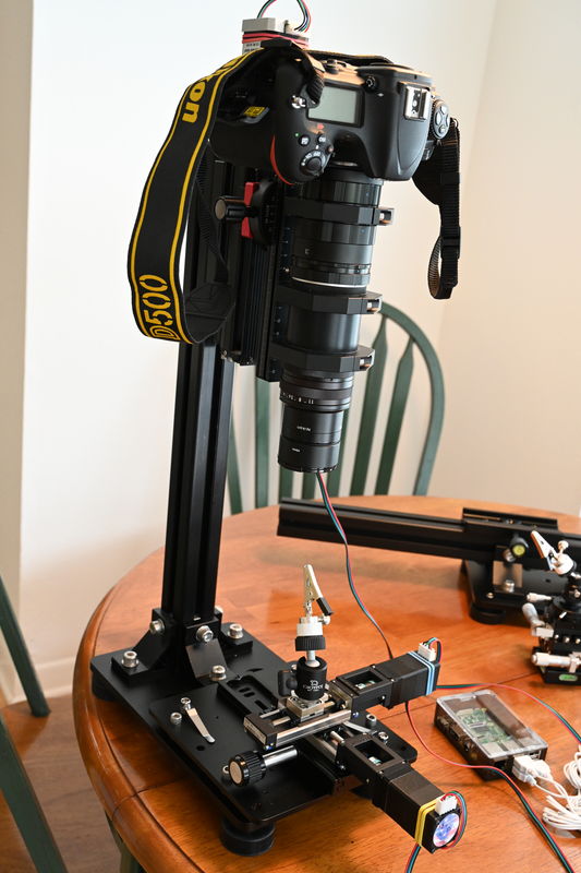
I decided to have the initial system be vertically based and move the camera/lens with a precision motorized rail for focus stacking and move the subject for the stitching regions with other less precise motorized rails. My precision setup is horizontally based, so I ordered a 95mm vertical extruded bar (Thor Labs) which is bolted to a sliding rail. The idea was to have the camera/lens attached to a motorized focus rail and move Z axis vertically mounted to this 95mm bar. The subject would be mounted to a X and Y positioning motorized rails, which can be less precise. Then I realized I could use the Wemacro Vertical Stand for this as well, so I decided to use the Wemacro setup as my developing setup rather than the Thor Labs setup, since the Wemacro is smaller and portable.
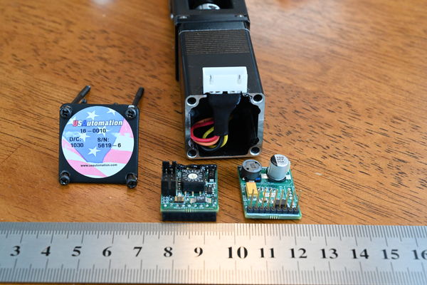
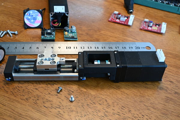
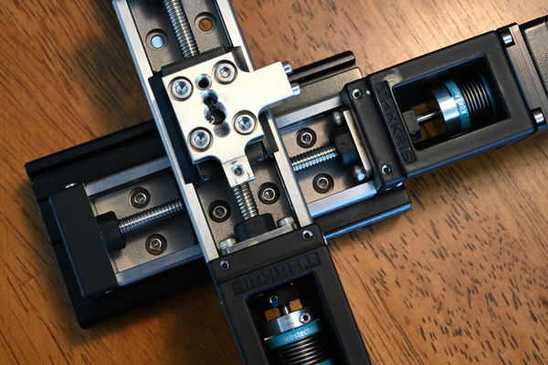
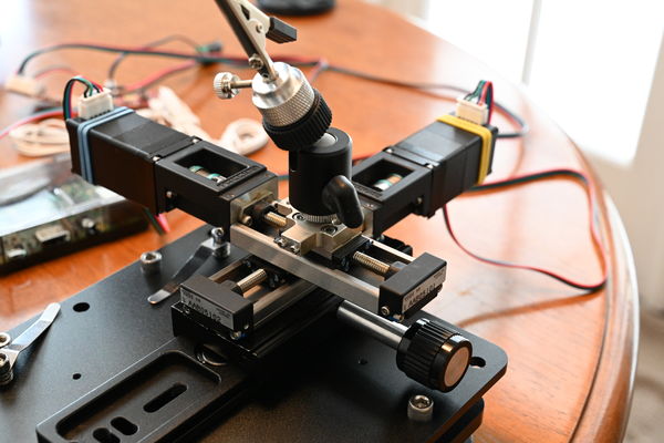
Small motorized rails were what I wanted for the X and Y stage, I could (and did) use larger rails but they were too big and awkward for my usual subjects (Silicon chips). Ebay came to rescue with some small US Automated THK KR15s. These are nice small rails that with a little work can be modified for our macro use, please see the other threads for details. I removed the electronics and wired the stepper motor to an external connectors as shown. I need 2 stepper rails for X and Y and mounted one KR-15 on top the other at right angles, the bottom KR-15 is directly mounted to a long ARCA clamp.
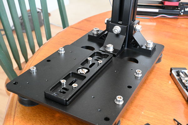
Now mounting this X & Y setup to the Wemacro base was by way of a secured (4 M5 bolts) ARCA plate attached to a Wemacro plate that bolts (4 1/4-20 bolts) to the base as shown. The Z axis is handled by the standard Wemacro setup using a THK KR20 (or 26) bolted to a ARCA plate, the THK KR20 is a slightly larger rail than the KR-15 and a good choice for handing the camera and lens assembly.
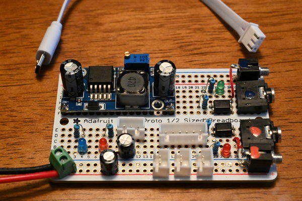
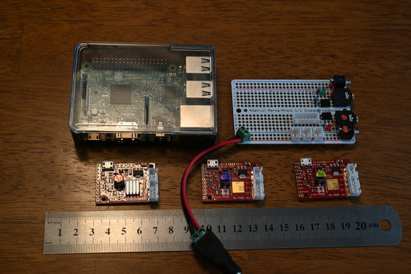
For the electronics the Raspberry Pi was chosen as the base computer, with Pololu Tic-500 as the motor controllers (3). For triggering the camera (and strobes) an optical isolated circuit was used and this allows separate triggering of the strobe/flash without using the camera hotshot. Almost all cameras EFCS and ESCS (all electronic shutter) blocks Hot Shoe triggering during this mode, the work around is to create a separate trigger for the strobe/flash that places the exposure within the shutter opening.
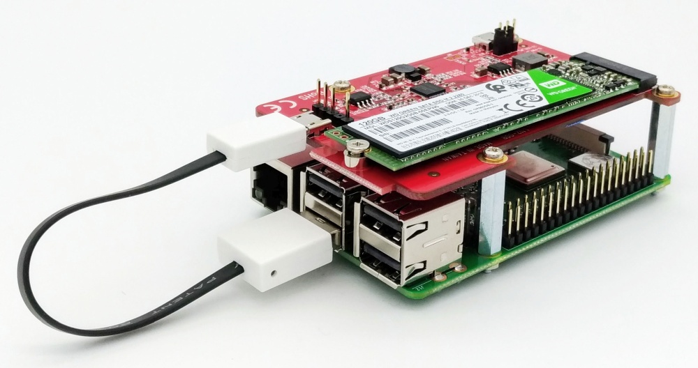
Operating software was created on the Raspberry Pi 3B in Python, these are amazing computers and only cost $35!! Even the tiny $10 Raspberry Pi Zero W will run the entire setup without issue (a little slow though). These Raspberries can operate under VNC mode where no monitor, keyboard or mouse is required with the Raspberry, you have a true remote desktop application which can operate anywhere within your router range!! All 3 Tic-500s are connected by USB, these are splendid controllers (from the folks from MIT, as is Python I believe) that can operate just about any stepper motor system that a macro photographer would need. They have a mode where the motor currents are partially recycled back to the power supply rather than wasted to ground, this allow the entire system, including Raspberry Pi 3B and all controller and electronics, 2 NEMA 11 Stepper motors (KR-15) and a NEMA 17 Stepper motor (KR-20) to operate from a single 12 volt 2.5 amp supply!!
For more details on the development & components of this system and the Thor Labs setup please use the links provided.
Anyway, I hope this helps some DIYers with limited resources (like me!) that may be thinking of tackling a project like this...you can do it!!
US Automation THK KR-15
(Download)
US Automation THK KR-15
(Download)
KR-15 Mounted on top another with ARCA clamp below
(Download)
ARCA Plate attached to Wemacro base
(Download)
X and Y KR-15 Mounted on Wemacro base
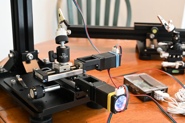
(Download)
X and Y KR-15 Mounted on Wemacro base
(Download)
Wemacro Vertical Stand with X and Y USA KR-15s
(Download)
Trigger electronics and 12v to 5 v converter
(Download)
Raspberry Pi 3B, 3 Pololu Tic-500 and early version of Trigger Circuit (no converter)
(Download)
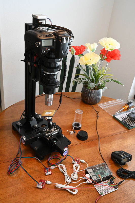
Everything connected up
(Download)
Best,
--
Research is like a treasure hunt, you don't know where to look or what you'll find!
~Mike
As somewhat of a followup to this older thread on another site regarding modifying the Wemacro Vertical Stand for horizontal use, I've been developing a S&S setup based upon the Wemacro Vertical Stand and a Precision Thor Labs setup.
https://www.uglyhedgehog.com/t-539182-1.html
You can follow the details in these threads below at PM.
https://www.photomacrography.net/forum/viewtopic.php?t=38511
https://www.photomacrography.net/forum/viewtopic.php?t=38512
https://www.photomacrography.net/forum/viewtopic.php?t=38548
Stack and Stitching involves taking multiple image focus stacks, usually with somewhat high magnifications, then move the camera/lens and/or subject and repeat. You end up with a bunch of images that need to be first focus stacked using specialized software (Zerene for example) at each location, then the post stacked images are stitched together like a panorama. The resultant final image has very high resolution, much more than a normal camera/lens can deliver, but utilizes available components. I have done this (~19000 X 13000 pixels) partly manually, and can tell you first hand it's very time consuming and tedious.
Commercial systems are available to help, but are expensive, and some have limited computer compatibility. So after doing a few S&S sessions manually, I decided to attempt with my cheap Harbor Freight drill press, a few drills and taps, and a soldering iron to create my own precision S&S system. I also don't have any programming skills, and my computer knowledge is quite limited!!
I've spent lots of time "thinking" about how I wanted things to work and decided not to use available software or other techniques...I wanted this work the way I wanted rather than adapted to "fit" another protocol.
I decided to have the initial system be vertically based and move the camera/lens with a precision motorized rail for focus stacking and move the subject for the stitching regions with other less precise motorized rails. My precision setup is horizontally based, so I ordered a 95mm vertical extruded bar (Thor Labs) which is bolted to a sliding rail. The idea was to have the camera/lens attached to a motorized focus rail and move Z axis vertically mounted to this 95mm bar. The subject would be mounted to a X and Y positioning motorized rails, which can be less precise. Then I realized I could use the Wemacro Vertical Stand for this as well, so I decided to use the Wemacro setup as my developing setup rather than the Thor Labs setup, since the Wemacro is smaller and portable.
Small motorized rails were what I wanted for the X and Y stage, I could (and did) use larger rails but they were too big and awkward for my usual subjects (Silicon chips). Ebay came to rescue with some small US Automated THK KR15s. These are nice small rails that with a little work can be modified for our macro use, please see the other threads for details. I removed the electronics and wired the stepper motor to an external connectors as shown. I need 2 stepper rails for X and Y and mounted one KR-15 on top the other at right angles, the bottom KR-15 is directly mounted to a long ARCA clamp.
Now mounting this X & Y setup to the Wemacro base was by way of a secured (4 M5 bolts) ARCA plate attached to a Wemacro plate that bolts (4 1/4-20 bolts) to the base as shown. The Z axis is handled by the standard Wemacro setup using a THK KR20 (or 26) bolted to a ARCA plate, the THK KR20 is a slightly larger rail than the KR-15 and a good choice for handing the camera and lens assembly.
For the electronics the Raspberry Pi was chosen as the base computer, with Pololu Tic-500 as the motor controllers (3). For triggering the camera (and strobes) an optical isolated circuit was used and this allows separate triggering of the strobe/flash without using the camera hotshot. Almost all cameras EFCS and ESCS (all electronic shutter) blocks Hot Shoe triggering during this mode, the work around is to create a separate trigger for the strobe/flash that places the exposure within the shutter opening.
Operating software was created on the Raspberry Pi 3B in Python, these are amazing computers and only cost $35!! Even the tiny $10 Raspberry Pi Zero W will run the entire setup without issue (a little slow though). These Raspberries can operate under VNC mode where no monitor, keyboard or mouse is required with the Raspberry, you have a true remote desktop application which can operate anywhere within your router range!! All 3 Tic-500s are connected by USB, these are splendid controllers (from the folks from MIT, as is Python I believe) that can operate just about any stepper motor system that a macro photographer would need. They have a mode where the motor currents are partially recycled back to the power supply rather than wasted to ground, this allow the entire system, including Raspberry Pi 3B and all controller and electronics, 2 NEMA 11 Stepper motors (KR-15) and a NEMA 17 Stepper motor (KR-20) to operate from a single 12 volt 2.5 amp supply!!
For more details on the development & components of this system and the Thor Labs setup please use the links provided.
Anyway, I hope this helps some DIYers with limited resources (like me!) that may be thinking of tackling a project like this...you can do it!!
US Automation THK KR-15
(Download)
US Automation THK KR-15
(Download)
KR-15 Mounted on top another with ARCA clamp below
(Download)
ARCA Plate attached to Wemacro base
(Download)
X and Y KR-15 Mounted on Wemacro base
(Download)
X and Y KR-15 Mounted on Wemacro base
(Download)
Wemacro Vertical Stand with X and Y USA KR-15s
(Download)
Trigger electronics and 12v to 5 v converter
(Download)
Raspberry Pi 3B, 3 Pololu Tic-500 and early version of Trigger Circuit (no converter)
(Download)
Everything connected up
(Download)
Best,
--
Research is like a treasure hunt, you don't know where to look or what you'll find!
~Mike
Last edited:


, D850, Nikkor 105mm, Pololu Tic-500, Raspberry Pi Zero W")


")
")


 and Voltage (12~24V) Controller with discrete MOS FET devices")
 and Voltage (12~24V) Controller")
")
")


")
")


 0.9 Degree Stepper motor")
")
